Part One: Introduction
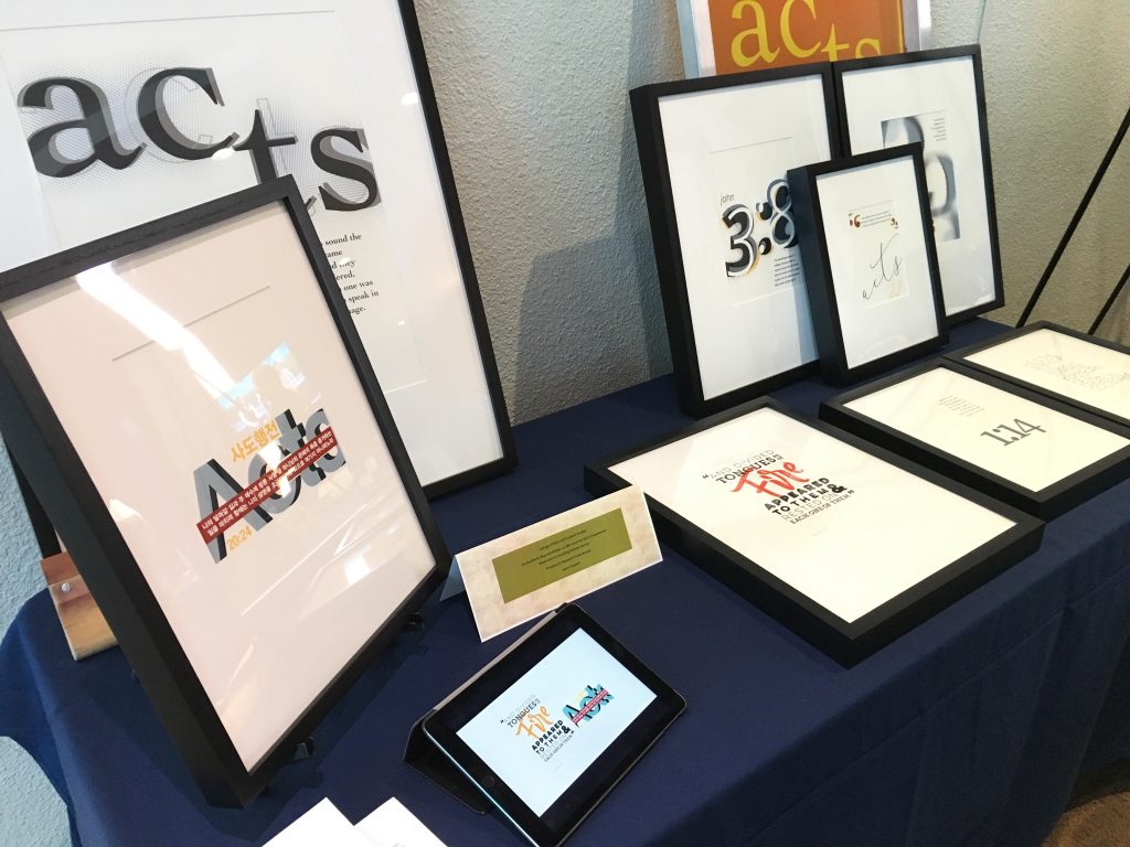
In summer of 2017, I received funding from Oral Roberts University (ORU) President’s Research Fund to pursue prints using Biblical verses as the content and contextual basis. As visual forms increase in frequency, yet decrease in literacy, a visually dominant presentation of Scripture is needed reengage present, and more importantly future, viewers with the significance of the Spirit-Empowered movement’s foundational verses. The creation of this series of prints sought to glorify and modernize the beauty of the literal word of God as presented in the Bible can address this cultural gap. The utilitarian nature of most bibles hides the elegance and grace of the aesthetic minutiae of letters, words and passages. The grant funded the creation and production of a series of visually engaging prints distributed in support of the university and the Spirit Empowered Movement.
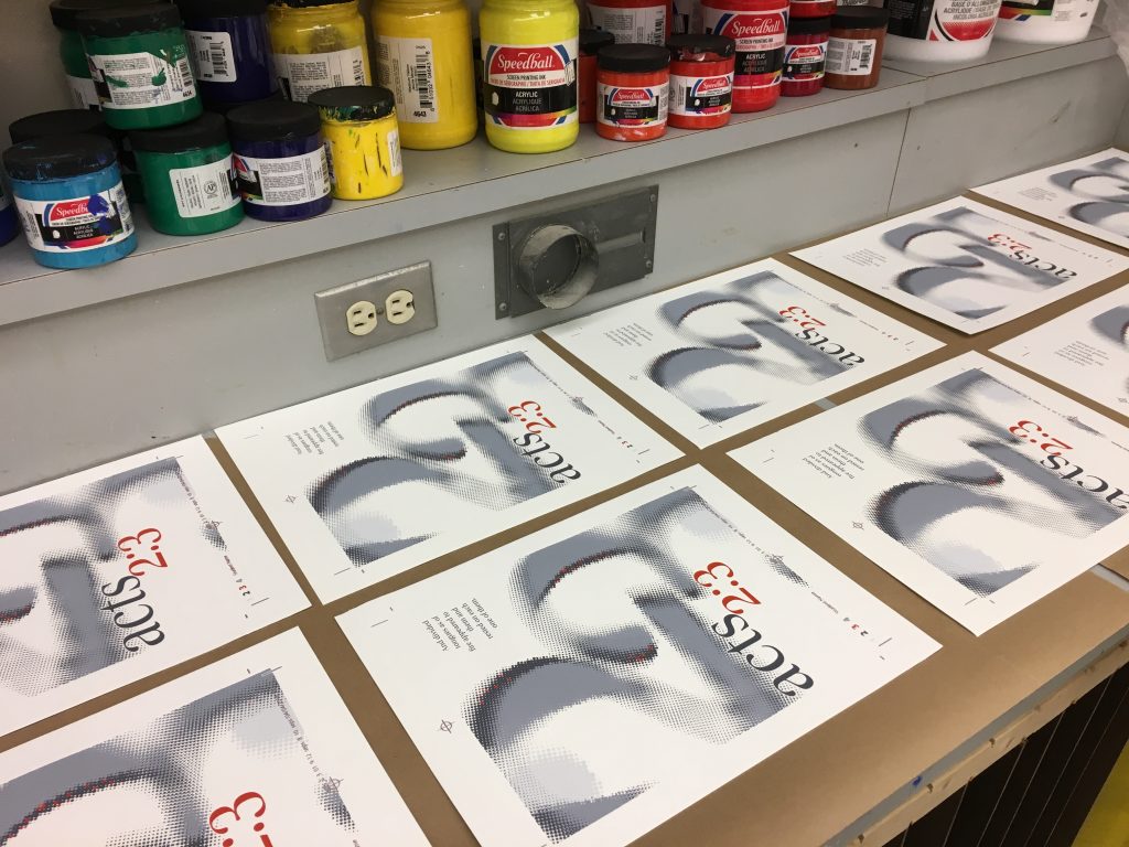
The result was a series of prints, created by myself as the primary investigator, but also designed by and produced in languages spoken by ORU students. The form of the prints began to explore the visual attributes, print materials, production techniques and final scale of screen print and letterpress compositions. Documentation of the experience took several forms, including campus presentations, exhibitions and a more thorough account published at here.
Part Two: Research and Needs Assessment
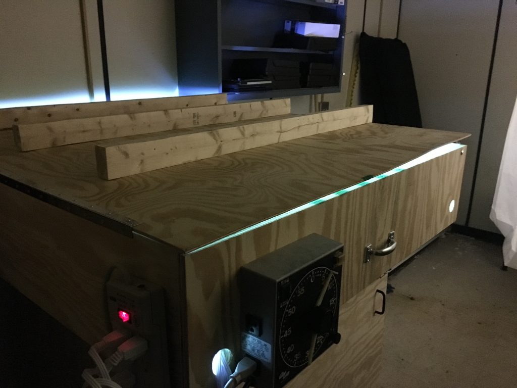
In the spring on 2017, I was asked to teach an ad hoc screen print course. With over 20 students registered, I needed accessible, simple and repeatable solutions for the process. I was able to utilize some unused darkroom and graphics production spaces from at least the late 1980’s at the university to create a semi-dark room, washout area, drying cabinet and light table. It was during this time, I began to think large, and planned for the future possibility of printing up to a 48 x 36 in screen. For smaller students, the leverage angles and forces needed to produce an adequate large scale manual print were too great. Some of the observed quality issues were due to screen size and poor exposure, but consistency of the print stroke was obvious once other variables were removed. In addition precise registration is difficult as small adjustments become hard to manage 3–4 feet from the pivot point of the screen and registration clamps.
The cost for professional industrially manufactured, large format screen printing presses is quite large, in excess of $10,000. I did not feel I could justify the expense with my or the schools› money for the periodic use in class and research. I investigated a reasonable do-it-yourself solution to provide a higher level of printing than I had, but at a more reasonable cost. Using visible information of the TMI Jaguar press (http://www.tmiscreenprinting.com/products/tmi-jaguar-one-arm/), Paul Cretin›s one arm press (http://paul.cretin.net/onearm.html) and the Museum of Arts and Design’s collaboration with the UM Project (http://www.umproject.com/projects/#/the-print-shop/) I settled on a plan for a manual press utilizing a linear roller bearing track as the primary printing mechanism and clamshell motion to raise and lower the screen.
Part Three: Ideation and Planning
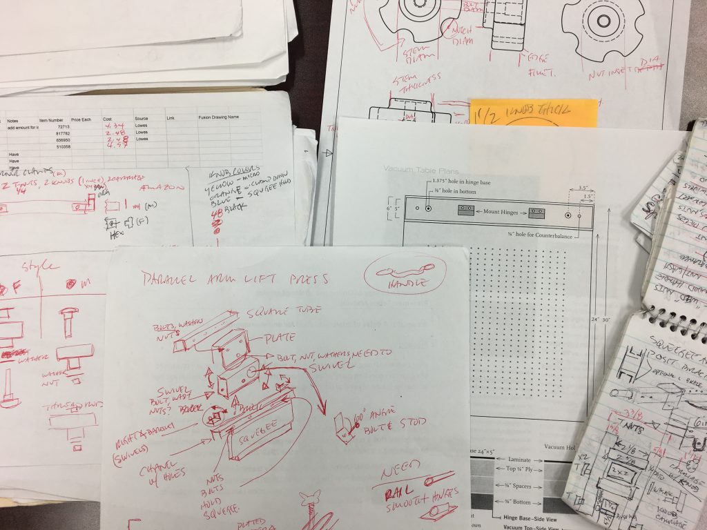
Given previous experience building presses for use in research and class, I used Andy MacDougal’s Rabbit press (http://www.tmiscreenprinting.com/products/rabbit-vacuum-tables/), also featured in his book Screen Printing Today – The Basics, as a basis. These presses consist of plywood and laminate to form a vacuum table to hold paper down, a hinge system to clamp the frames, and a counter balance system to hold the screen in the appropriate place during the print cycle. The press is simple and modular, making it an excellent foundation. Cretin’s linear rail system and the UM Project’s squeegee assembly provided the necessary movement during the print stroke. I began to sketch and determine specifications and ultimately started a purchase list of items I needed. A screw based system for registration was developed to assist with aligning the screens to each printed color, and integrated into the modified base plans. Supplies were ordered, and some allowance was made of intangible specifics and unknown variables.
Part Four: Prototyping and Testing
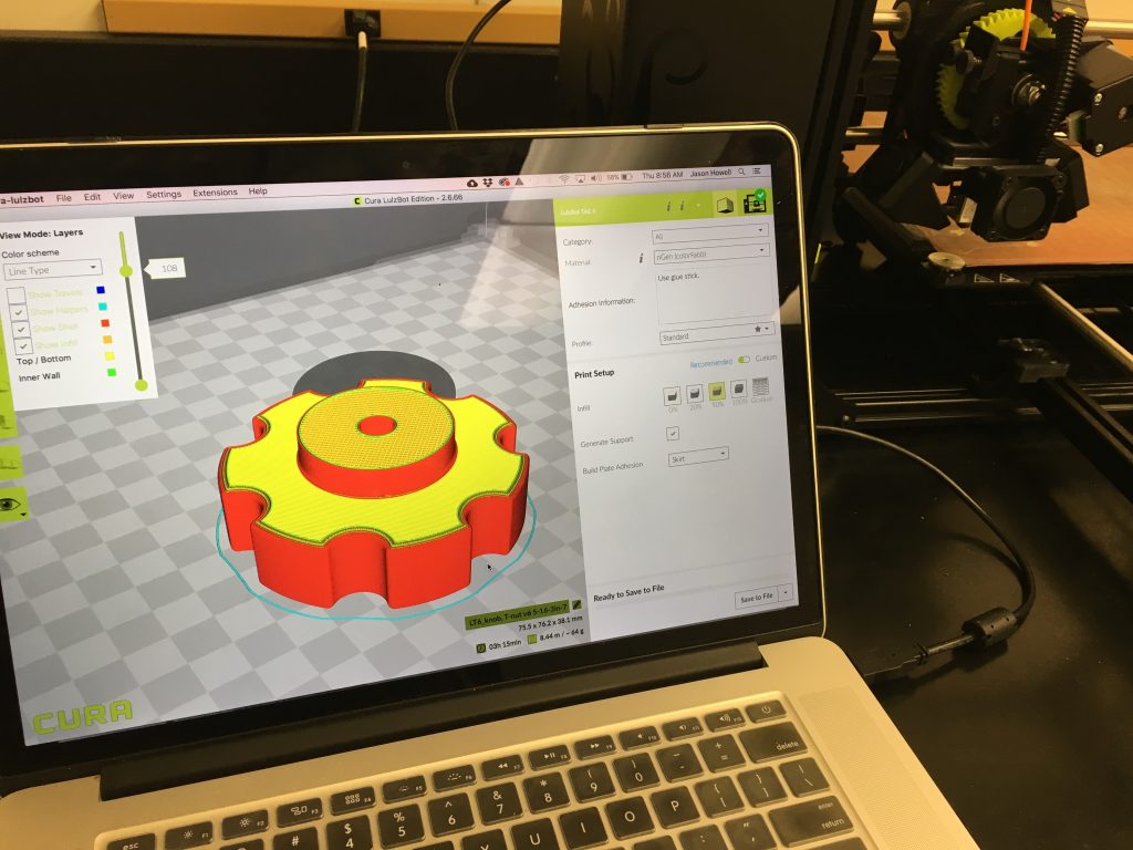
With the availability of digital fabrication tools, such as 3D printers and CNC routers, the fabrication of the press would be somewhat automated. A comparative process would utilize the best of each. I created a similar object out of multiple materials or processes and used that as a comparison. It seemed that attachment and hold down knobs would be he best choice, with some based on hex and carriage bolts, but others based on t‑nuts. The creation of each provided additional skills and knowledge of the equipment. Decisions were made on the results. CNC parts were created using Easel (https://www.inventables.com/technologies/easel) by Inventables on a 1000 mm X‑Carve (https://www.inventables.com/technologies/x‑carve) machine. Easel determined computer aided machining commands from imported SVG files, generated from Adobe Illustrator (https://www.adobe.com/products/illustrator.html). 3D printed parts were created using parametric modeling in Autodesk’s Fusion 360 (https://www.autodesk.com/products/fusion-360/overview). Model files were exported to Lulzbot’s version of Cura (https://www.lulzbot.com/cura), an open-source slicing and printing software sponsored by Ultimaker (https://ultimaker.com/en/products/ultimaker-cura-software), for slicing and determining the actions of the Taz 6 (https://www.lulzbot.com/store/printers/lulzbot-taz‑6) 3D printer. The holes need for the vacuum table were programed in Fusion 360 and tests were drilled using a modified Dremel (https://www.dremel.com/en_US/) tool and Printbot Crawlbot (https://printrbot.com/shop/printrbot-crawlbot/) CNC machine.
Part Five: Press Construction
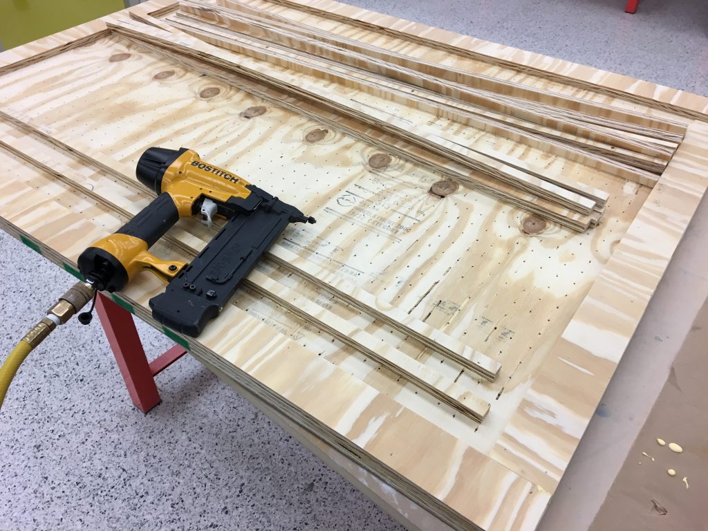
Press construction began with assembling as many materials and equipment as was reasonable for the space. Plywood parts, such as the base, spacers and the surface top, were measured and cut at a table saw. The laminate top surface was glued with contact cement and edged with flush trimming laminate bit. The approximately 1200 holes for the 36 x 48 in. vacuum table were mechanically drilled. A putty knife and fine sandpaper refined some slight errors and melting resulting in a less than flat surface. The base edges and spaces for vacuum nozzles were positioned, cut, glued and nailed. Seams were caulked, another layer of glue was applied and the press base was place upside down using reference lines. Nails and screws held the base and spacers to the top. Once dry, a support system was created to raise the base to make room for threaded rod needed for registration micro-adjustment. Holes were drilled, hardware assembled and the final plywood fastened to finish the base. The registration base was measured, cut and drilled. Holes fastening screen print hinge bolts were measured, drilled and used to install the hinges. All knobs for bolts and t‑nuts were 3D printed based on the Fusion 360 models, with attention to color, size and function.
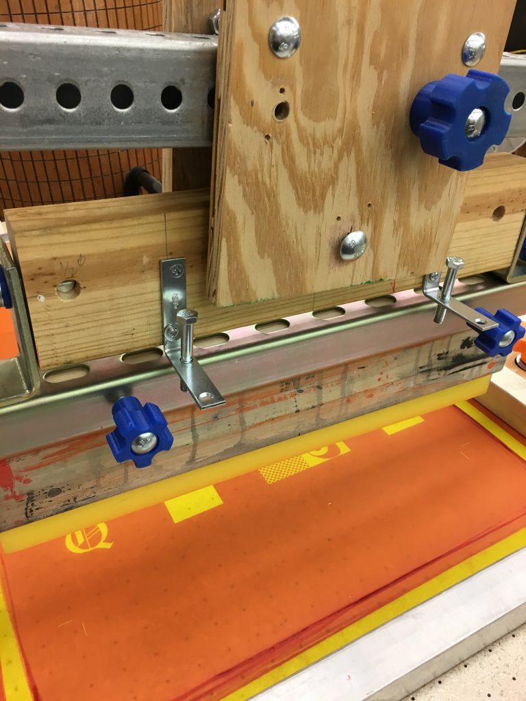
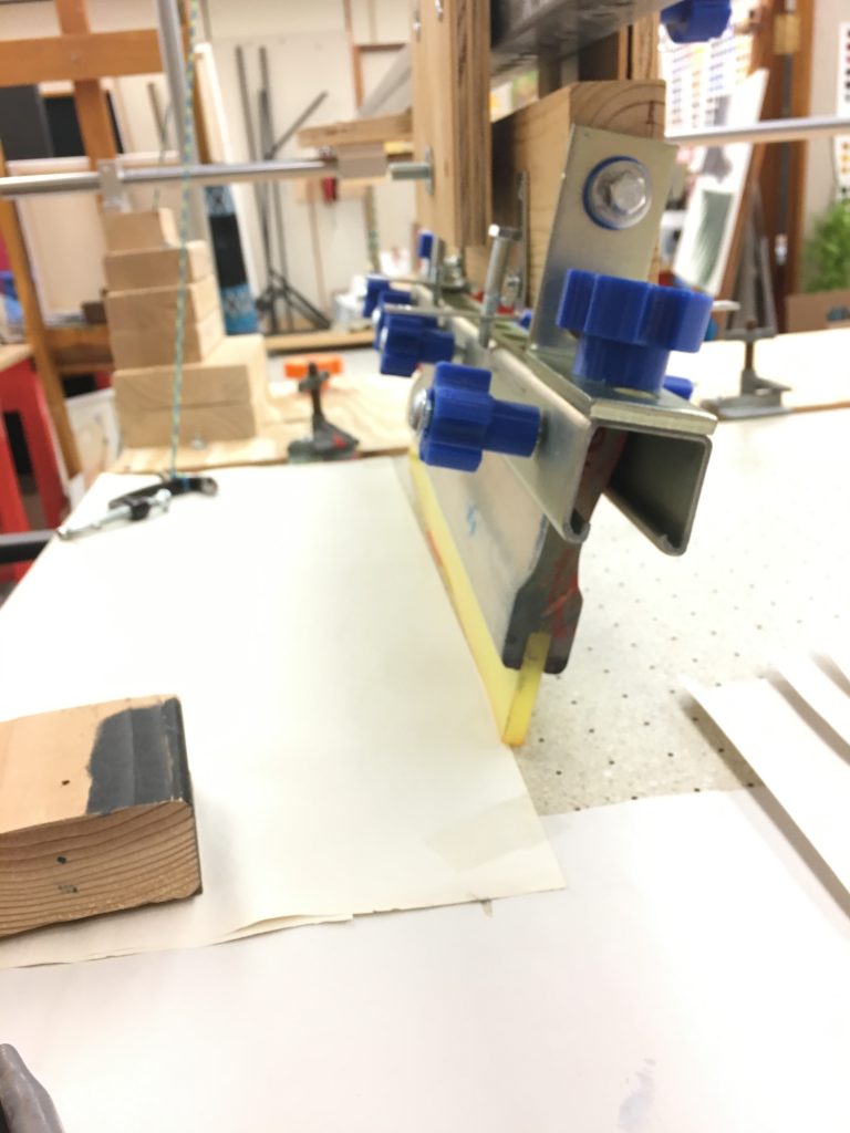
The mechanics of the squeegee position required an ability to adjust in two axes. A piece of strut channel would accommodate a number of squeegee sizes. The material also provided brackets and holes to make connections to the pivoting mechanism. Knobs and threaded holes allowed for easy removal of squeegee assembly for cleaning and reinstallation. Common pressure treated 2 x 4 in. lumber provided form in which multi-axis holes were drilled and hardware inserted. The squeegee needed rotation parallel to the screen during the print and flood strokes. Two “L” brackets on each side set end positions and used drilled and tapped through holes for bolts and knobs to fine-tune any distances. Spacers, nuts and slight modifications created a strong and repeatable movement.
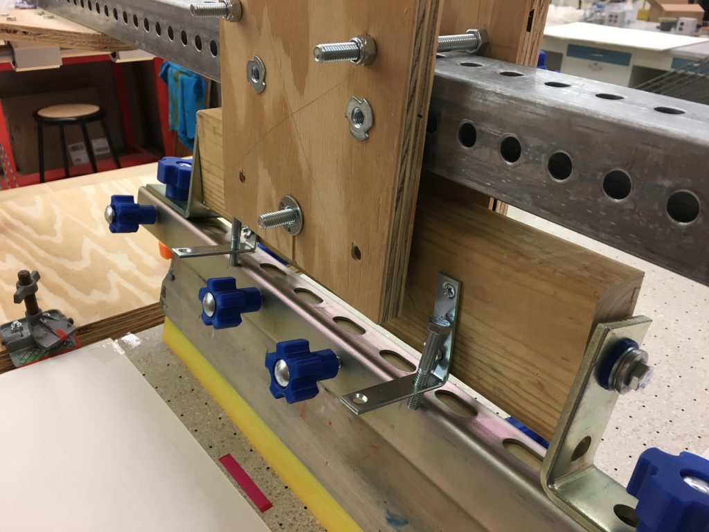
Close up view of linear rail assembly, used to adjust position of squeegee along y‑axis to accommodate various sized screens.
The ability to adjust the location of the squeegee along the print arm’s y‑axis to accommodate multiple sizes screens was developed during the planning stages. The print arm consisted of 2 in. perforated square tube, often used for supporting traffic signs. Plywood scraps would serve as the faces, with t‑straps handling the necessary forces. Alignment required drilling some coordinating holes and a series of carriage bolts, nuts and t‑nuts allowed for adjustment with the dimensions. A final position is locked down using carriage bolts, printed knobs and t‑nuts. The swivel mechanism’s position was based on holes in the straps, drilled, and assembled with a larger bolt and metal spacer washers to prevent hole from wearing out.
Once the heights of squeegee position and rotation were determined, the linear rail assembly and base was begun. A mounting board was cut using the X‑Carve out of scrap ¾ in plywood. The linear rail bearings were secured with machine screws in drilled holes and provided with some allowance to resolve any binding. Considerable time was spent deciding on the location and fastening mechanism for the rail. A simple solution of stacked scrap 2x dimensional lumber was used to generate the necessary height. The functional system was secured to the wood with ¼ in. lag screws of various lengths from top and countersunk on bottom. The counterbalance system was assembled using commercial electrical conduit and components, pulleys, nylon parachute cord and weighted, one-gallon containers.
Part Six: Testing and Improvements
With all mechanical systems in place and basic functions tested, a fully functioning assessment of the press’ mechanics was needed. A screen was loaded and the counterbalance adjusted. Two vacuums were attached and provided sufficient suction to hold the paper substrate to the surface. A blank screen was used to create a solid flat block of color to determine any imperfections or variances in pressure during the print cycle. With no blemishes obvious, a second test using a preexisting screen was made. A comparison with the hand printed and machine printed sample artwork revealed no noticeable print quality differences. The press was ready for use.
Part Seven: Print Content
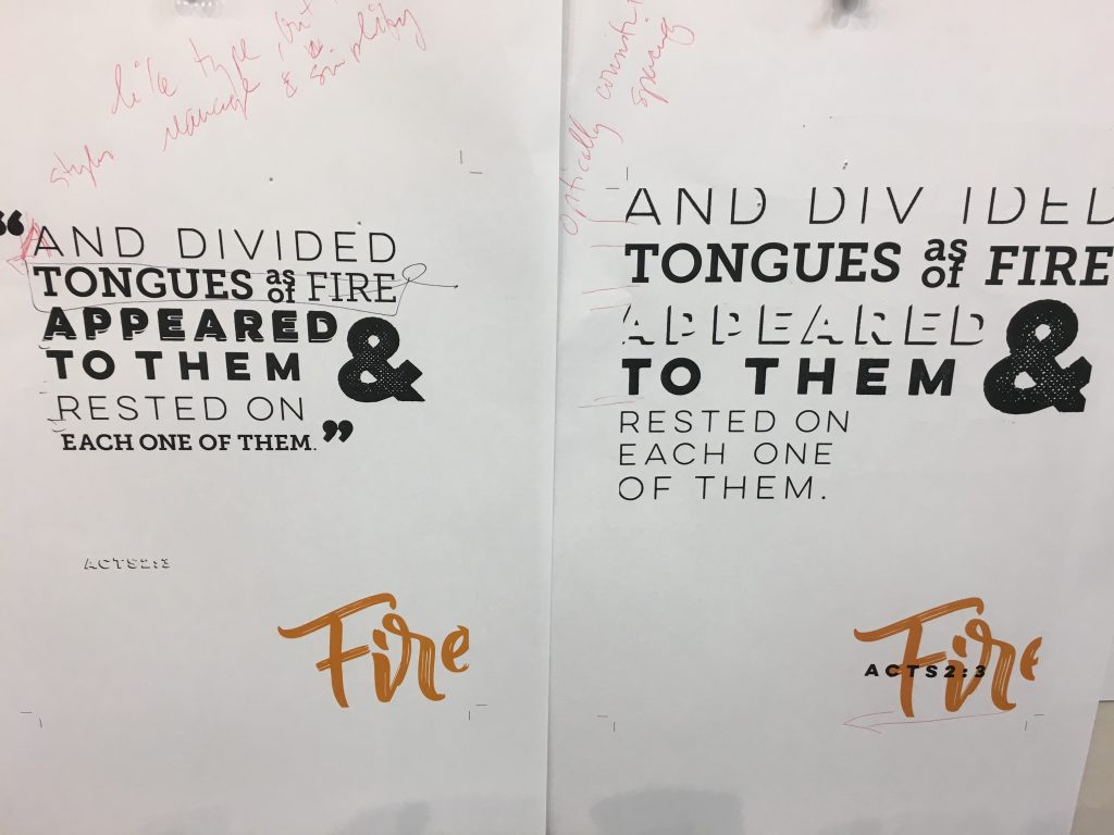
Parallel to the press planning and construction process, students and I began to develop content for printing. Students were selected for participation based on design experience, screen print knowledge, cultural and linguistic background. The goal of the project was to create contemporary biblical verses that support the historical and founding influences of the university. A selection of verses, mostly from Acts, was chosen, but students were also allowed to select any verse deemed appropriate to the project. Multilingual students were also encouraged to integrate colors, verses and typefaces into their solution from their specific background’s cultural traditions. A wide range of students was selected to serve as Student Research Assistants. Students discussed ideas and sizes with me and artwork was digitally submitted. Proofs were created to test color, review sizing and identify areas of refinement. Changes were made and finalized.
Part Eight: Print Process
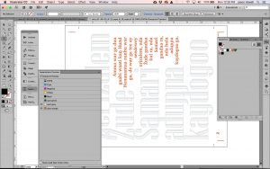
Digital file preparation and color separation using Adobe Illustrator for Acts 1:8, created by student Amber Teague.

Final separation films for Acts 1:8 created using Adobe Illustrator, Acrobat Distiller and output on Epson Stylus Pro 9900.
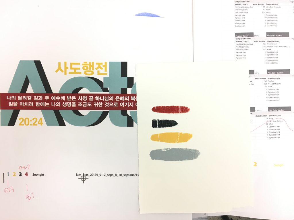
Using Adobe Illustrator, modifications were made to prepare the artwork’s colors, dimensions and format for printing. Films needed to create screen stencils were output using an Epson large format printer and special transparent film media. A screen for each printed color was coated with photosensitive emulsion and dried in a light safe cabinet until set for exposure. The films were positioned on the screen, and then placed on a ultra-violet light table for a specified timed period. Once exposed, the uncured emulsion was washed out to reveal a stencil for each color. Screens were then dried in preparation for printing.
Colors were mixed using a Pantone system of reference samples and formulas. Base ink colors were measured in proper proportions using a scale. Ink samples were made on test paper, and adjustments made to account for inaccuracies or conflicts. Dry screens were placed on the press bed, fixed with the hinge clamps and them registered to the paper and the films. The screen was prepared for printing on the press and each color printed during the run. Prints were dried, and the process repeated between two and four times per print, based on the total number of colors. Existing small presses was used for small prints, and the grant-funded press was used for prints larger than 16 x 20 in.
Part Nine: Conclusion
Once allowed sufficient time to dry, the finished prints were collected and signed by the artist. Mats were cut based on size of print and final frame dimensions, mounted using archival materials, and inserted into frames. Identification labels were digitally printed and affixed to a dust paper backing, which was applied to seal the print from further intrusion. Positions for hanging hardware were determined, and fastened to the back of each frame. Ten prints are stored with the Theatre, Dance and Visual Arts Department, and ten identical prints are stored and framed ready for display at the Provost’s space of the sixth floor of the Graduate Center, or at other locations on campus. The remaining 80 prints are stored unmatted and unframed in the Theatre, Dance and Visual Arts Department until distribution is requested.
Overall, the grant provided material, equipment and student support to produce several noteworthy pieces. Many prints are in the process of being submitted for possible exhibition, through various venue’s open call for entries using a peer review process. The project was also provided support for application to “Matter and Spirit: A Seminar on Contemporary Chinese Art and Society” hosted by Calvin College and “Expanding” hosted by 1920 Gallery and Indiana Wesleyan, though unfortunately, both applications were unsuccessful in gaining acceptance.
The process of planning and building equipment for making art provided necessary skills for future classroom instruction and interdisciplinary projects. Time limitations prevented a greater number of large format prints from being produced, as well as using digitally carved relief blocks, letterpress typefaces and relief presses to create similar printed compositions. The project provided knowledge and experience for teaching the use of digital fabrication tools to students, who can then use the classroom activities during their careers. The personal and profession growth that was a result of this project was immense, and I am grateful of the opportunity. It is with thanks to the appropriate administrative and funding parties that I will continue to pursue this track of creative research into the future.
